intermatic photocell wiring diagram
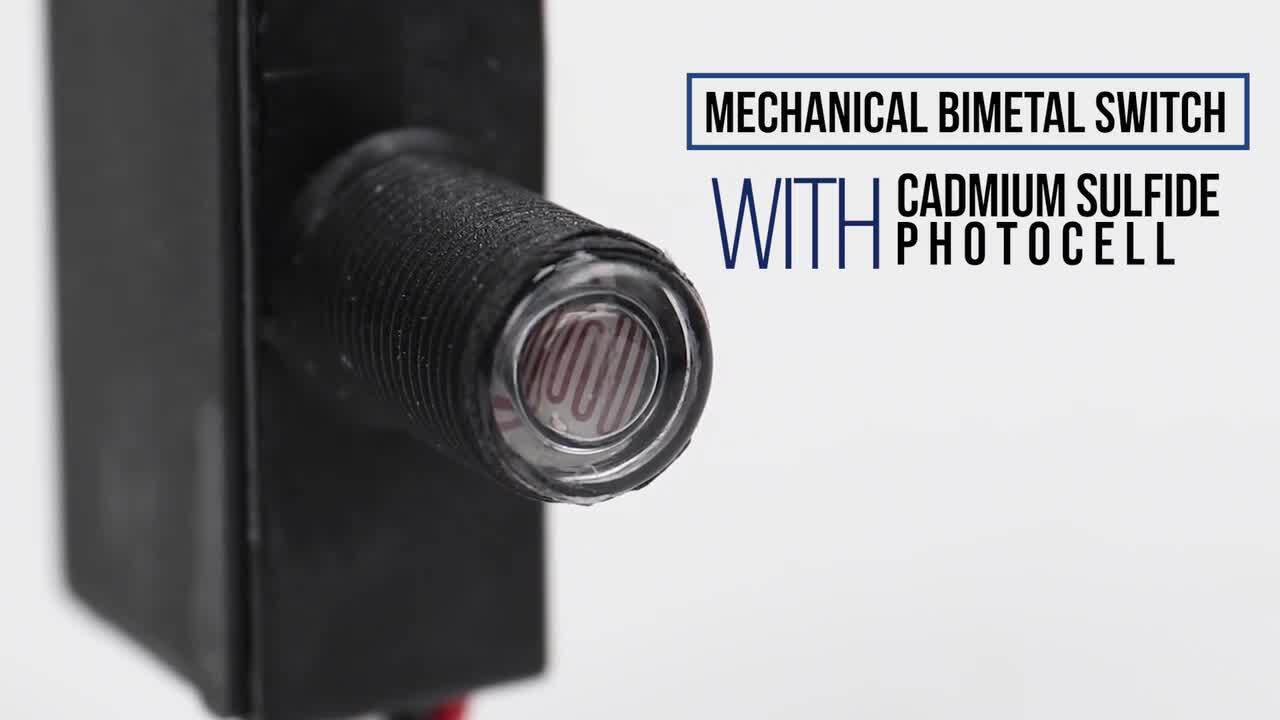
PHOTO CONTROLS Fixed Position Mounting Watts Tungsten VA Ballast AMPS Tungsten AMPS Ballast Not UL or CSA Certified. For instance when a module is usually.

Intermatic K4000 Thermal Photo Control Instruction Manual Manuals
Lap Rd0006 Indoor And Outdoor Black Photocell Sensor Instruction Manual Manuals.

. Effectively read a cabling diagram one has to learn how typically the components inside the system operate. And wiring diagrams. Fixed Mount Electronic Photocontrols.
Feed the photocell and clock motor with line and neutral this often entails taking the motor lead off the contcat terminal run the load of the photocell thru the clock contacts. Wiring diagram intermatic photocell volt control 240 t103 timer lighting contactor pool clock circuit 220v cell light air transformer pump. Shop for Intermatic K4221C thermal.
HOW DOES A PHOTOCELL WORK. March 16 2019 april. Intermatic Introduces New Installer.
Photocell Light Sensor Wiring Diagram. Electronic Ballast Load Ratings Ranges. As you tackle your summer to-do list consider these practical Intermatic project ideas to enhance your home and realize lasting energy savings.
Lighting Contactor Wiring Diagram With Photocell. Refer to the wiring diagrams below and choose the appropriate diagram. Wiring Diagram For Metal Halide Ballast With.
Photo Control Switch Type. Intermatic Photocell Wiring Diagram. And wiring diagrams K4021 K4321 K452 K1221 LC4521C FEATURES BENEFITS 5 Year Warranty NEMA twist lock plug connection.
Intermatic St01 3 Way Wiring Diagram. Stem and Swivel Mount. Explore our catalog of courses to learn about Intermatic Electrical HVACR Pool Spa and Utility products.
Intermatic Timer Wiring Diagram St01. US STORE httpamznto2hAQZ05 UK STORE httpsa. Intermatic photocell wiring diagram.
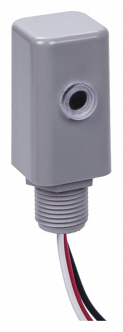
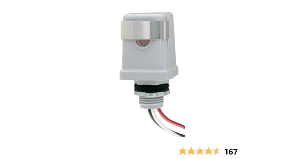
Deliver simple dusk-to-dawn lighting control with our lineup of fixed mount electronic photocontrols. Input Voltage Range s 120 VAC 5060 Hz. Intermatic Photocell Wiring Diagram.
Wiring a photo cell is explained in the video. Led shoebox light wiring diagram with photocell sensor to control several gate faac. 21 posts related to Intermatic 480v Photocell Wiring Diagram.
These LED compatible solutions are available in a. 2 sec to 5 sec OFF. 6 A 120-277 VAC 5060 Hz.
This photocell is used to control ou. Shop for intermatic k4221c thermal type photocell. 480v Photocell Wiring Diagram.
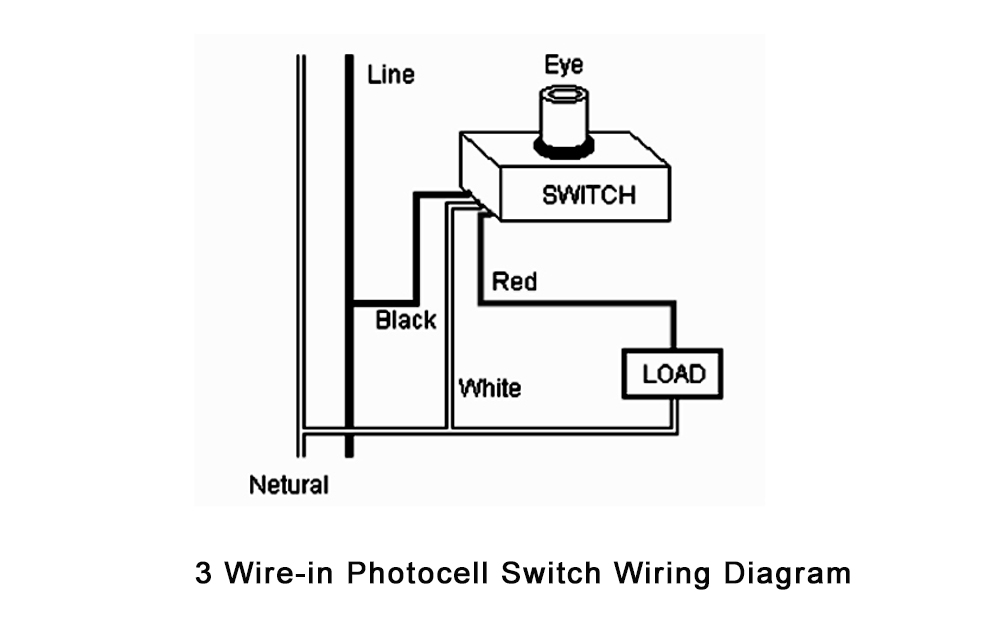
We show you where to attach the red wire the black wire and the grounds. Lighting Contactor With Photocell Wiring Diagram. Input Voltage Range s 120 VAC 5060 Hz.
007827500201 intermatic photocell dusk to.

Photocells Lighting Supply Guy
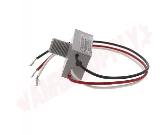
K4021 Intermatic Fixed Position Photocell 1800w 120v Amre Supply

Photocell Sensor Wiring Diagram Instruction

Main Stem And Swivel Mount Thermal Photocontrol 120 V
Reviews For Intermatic 500 Watt 120 Volt Dusk To Dawn Light Control Mini Button Photocontrol Black Pg 3 The Home Depot
Intermatic Photocontrol 105 To 305v Ac 1 000 Max Watt 15 A Max Incandescent Amps 1 5 2 25 52ru69 Ek4136s Grainger

Intermatic K122 Pole Bracket Adapter Color Brackets Amazon Canada

Intermatic Photocontrol Repair Intermatic Photocell Repair How To Wire A Photocell Light Sensor Youtube

Anschlusskabel Fur Ip44 Nemo 1m Schwarz 2 X 0 75 Mm Von Ledscom De
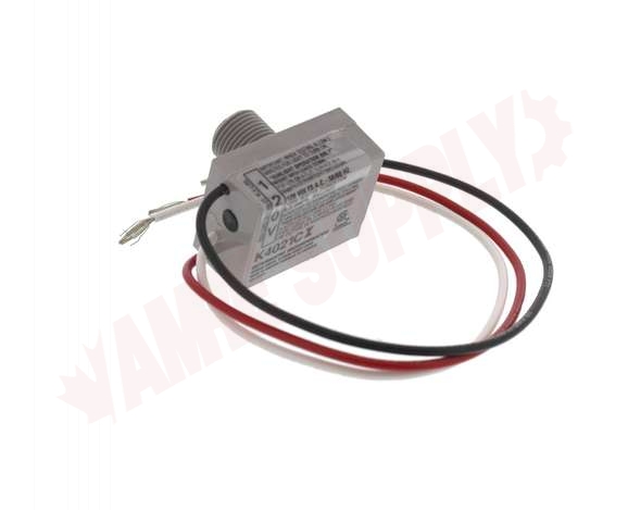
K4021 Intermatic Fixed Position Photocell 1800w 120v Amre Supply

Intermatic K4021c Usalight Com
Intermatic K4141c 120 Volt 25 Amp Stem Mount Thermal Photocontrol Gray Photocell Sensor Light Control Amazon Com

How To Wire A Photocell Eye For A Light Youtube

Photocell Wiring Photocell Wiring Diagramhow To Install Photocell How Photocell Works Nema Photocell Youtube

Ek4436sm Nightfox Metal Stem Mount Electronic Photocontrol

Intermatic Ek4536 Side Turn Lock Photocontrol 105 To 305 Vac 1800 Va Tungsten 1000 W Ballast Twist Lock Mount Polypropylene
Longjoin光控器 路灯光控器 Photocell Sensor 上海朗骏智能科技有限公司官网